

Basics Library
Build with Basics
Basics contains engine-native building blocks you can add without uploading a model. Use them to block out a level, light a scene, create paths, and define playable areas.
What is included
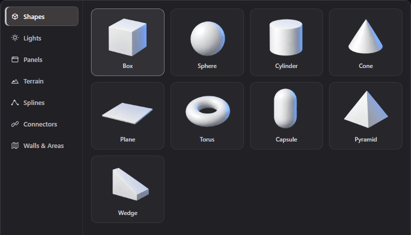
Shapes
Box, Sphere, Cylinder, Cone, Plane, Torus, Capsule, Pyramid, Wedge
Lights
Point, Spot, Directional, Area, Ambient, Hemisphere
Panels
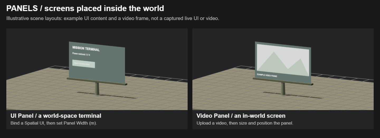
UI Panel, Video Panel
Terrain
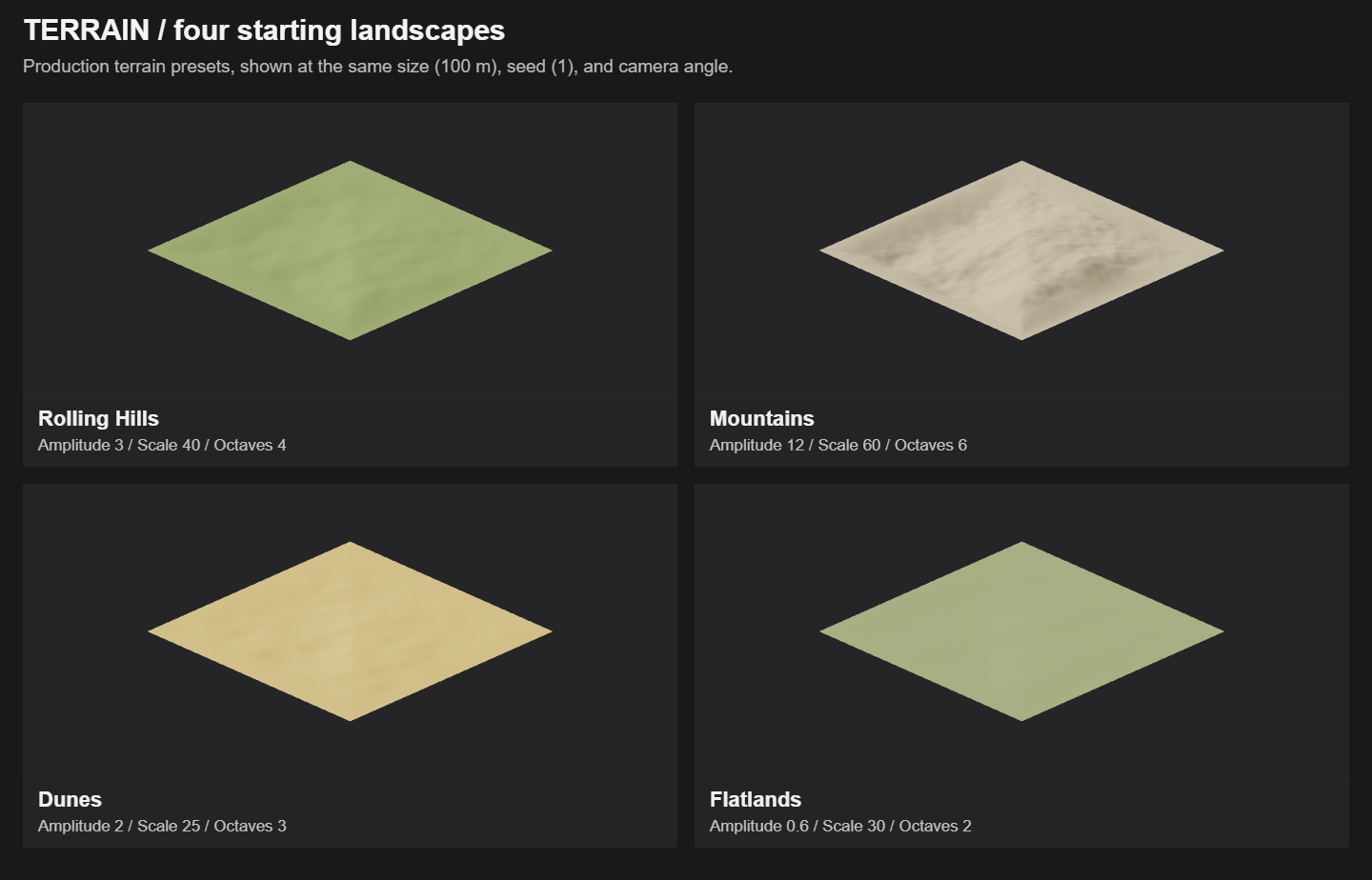
Rolling Hills, Mountains, Dunes, Flatlands
Splines
Line, Curve, Circle
Connectors
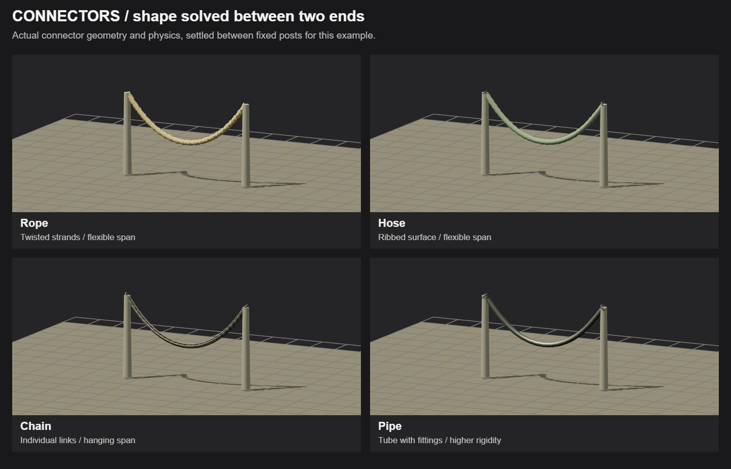
Wire, Rope, Cable, Hose, Pipe, Chain
Walls & Areas
Collision Wall, Navmesh Area
Place or draw
- Shapes, lights, panels, terrain, splines, and connectors are placed with Add or a double-click.
- Collision Walls and Navmesh Areas use Draw. Click points on the world surface, then press Done.
- Select the new item in the world to adjust its dimensions, material, light, terrain, path, or connector settings.
Spline preview behavior
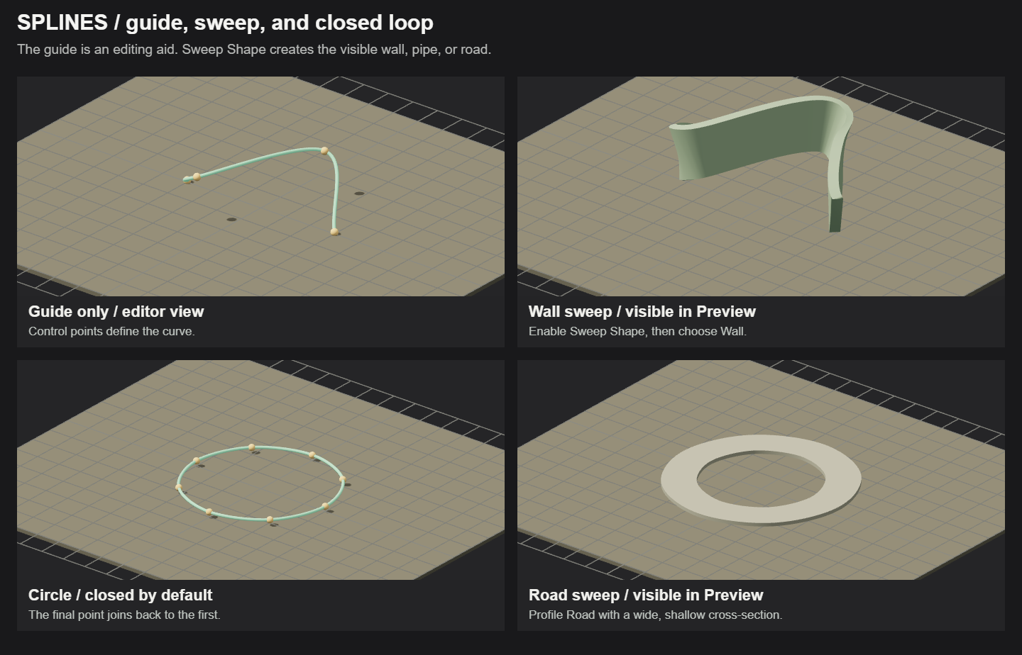
The Circle preset starts as a closed circular curve. Spline guides and edit handles are editor-only and hide in Preview mode; geometry created with a spline sweep remains visible.
Shapes: build the structure of a scene
Use simple geometry for floors, walls, platforms, ramps, and placeholder props. A shape is a visible world item: resize it, give it a surface, and configure collision to make it part of your level.
Try it in your scene
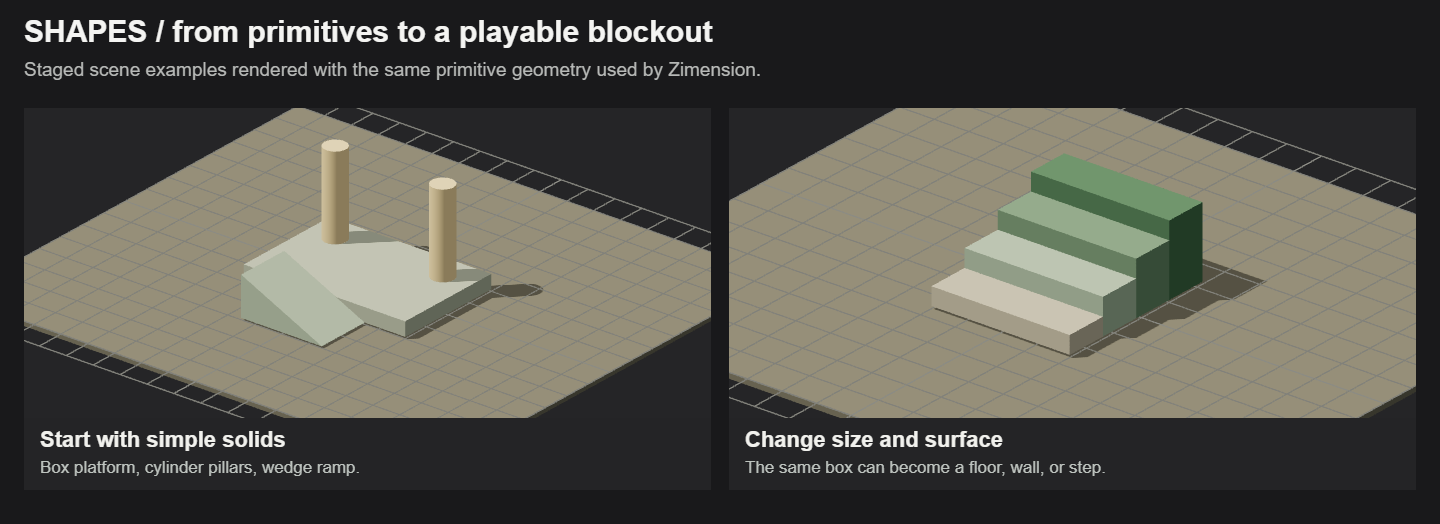
- Open Basics → Shapes, choose Box, and click Add Box.
- Select the box in the scene. Set Width and Depth to make a platform, then reduce Height.
- Add a Wedge for a ramp and Cylinders for pillars. Move and rotate the pieces into place, then test the route in Preview.
Settings that change the result
| Setting | What it does |
|---|---|
| Dimensions | Width, Height, Depth, Radius, and other controls depend on the shape. Use them to define the object before positioning it. |
| Segments | More segments make curved surfaces rounder, but add geometry. Boxes and wedges do not need this control. |
| Material / texture | Choose a material, upload a texture, or select an available animated surface. Keep Texture Size maintains texture scale when the shape is resized; Texture Repeat controls tiling. |
| Color, Roughness, Metalness | Color tints the surface. High Roughness makes it matte; Metalness changes the material toward a metallic response. Reflections depend on the scene lighting. |
| Emission / transparency | Emission makes the surface look luminous; it does not replace a light that illuminates nearby objects. Transparent and Opacity control see-through surfaces. |
Check the item’s Collision settings when building floors and ramps. A visible surface and a correctly shaped collider are separate things; test walking on the result.
Lights: control where illumination comes from
A light changes the appearance of other surfaces. Choose its type for the coverage you need, then adjust position, direction, color, and brightness. The editor helper marks the light; it is not a lamp model.
Try it in your scene
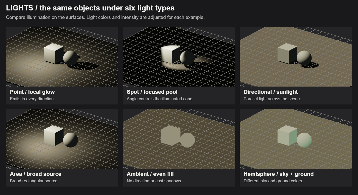
- Add a Point Light for a lamp or a Spot Light for a focused pool of light.
- Move it above or beside an object. Rotate Spot or Directional lights to aim them, then adjust Intensity until surface detail is visible.
- Use a small amount of Ambient or Hemisphere fill if unlit faces are too dark. Enable Cast Shadow where supported and inspect the result in Preview.
| Light type | What it does |
|---|---|
| Point Light | Emits in all directions from one position. Use for bulbs, lanterns, or small local lights. |
| Spot Light | Emits a cone. Use for stage lights, ceiling spots, or a focused highlight. Rotate to aim it. |
| Directional | Provides parallel illumination across the scene, like sunlight. Direction matters more than distance from the subject. |
| Area Light | A rectangular light source. Use for broad window or studio illumination; Width and Height set the source size. |
| Ambient | Adds the same fill everywhere. It has no direction and does not create cast shadows. Too much makes objects look flat. |
| Hemisphere | Blends upper-sky and lower-ground colors according to surface orientation. Use for outdoor fill; it does not create cast shadows. |
Settings that change the result
| Setting | What it does |
|---|---|
| Show Light / Color / Intensity | Switch illumination on or off, tint it, and set brightness. Different light types use different intensity ranges; do not copy a Point value directly to Ambient. |
| Distance / Decay | For Point and Spot: Distance limits the reach (0 means no distance cutoff); Decay controls how brightness falls with distance. |
| Angle / Penumbra | For Spot: Angle widens or narrows the cone. Penumbra softens its edge; a low value gives a harder edge. |
| Width / Height / Ground | Width and Height belong to Area lights. Ground is the lower color of a Hemisphere light. |
| Cast Shadow | Shadow support depends on the light and rendering mode. Point, Spot, and Directional can cast shadows; Ambient and Hemisphere cannot. Do not rely on Area lights for shadows in WebGL. |
If a light seems ineffective, check Show Light, its position and direction, Intensity, and Distance. A very bright environment can conceal a local light’s effect. Unlit materials will not respond like lit surfaces.
Terrain: shape a landscape
Terrain creates a separate procedural surface that you can move and style. Rolling Hills starts gentle, Mountains uses greater height variation, Dunes uses low undulations, and Flatlands stays nearly level. Presets are starting settings, not fixed models.
Try it in your scene
- Open Basics → Terrain and add a preset, such as Rolling Hills.
- Select the terrain. Set Size for the area you need, then adjust Amplitude and Scale to shape the land.
- Change Seed to try another layout. Choose Ground Material or Match ground, then check slopes and the edge of the terrain in Preview.
Settings that change the result
| Setting | What it does |
|---|---|
| Amplitude | The strength of the height variation. Raise it for taller hills and deeper dips; set it to 0 for a flat surface. |
| Scale | The spread of the landforms. Larger values produce broader features; smaller values pack features closer together. This is different from the terrain’s overall Size. |
| Octaves | The number of layers of landscape detail. More layers add smaller variations on top of the main landforms. |
| Detail | The mesh resolution. Higher values make finer height changes possible but increase geometry. Raise it only when the scene needs the extra detail. |
| Size / Seed | Size controls the surface footprint. Seed changes the generated layout; keeping the same seed and settings reproduces the same terrain. |
| Ground Material / Match ground | Choose a surface material or copy the world ground’s material and surface settings. Match ground does not copy terrain shape; water and 3D grass are not supported by that copy action. |
| Texture Repeat / Color / Roughness | Adjust tiling, surface tint, and matte appearance. Available controls depend on whether you use a material or an animated shader. |
Start with low Amplitude when the player needs to cross the terrain. Mountains may need a gentler route. The perimeter blends back toward a flat edge so it can meet surrounding ground.
Panels: place UI and video in the world
Panels are screens positioned inside the 3D scene. Use a UI Panel for an interactive terminal, menu, or information board, and a Video Panel for a screen that plays uploaded video. A world-space panel has a position and physical size, unlike a screen overlay.
Try it in your scene
- For UI: add UI Panel, then choose a design from Spatial UI. If none exists, use Create a Spatial UI first.
- Set Panel Width (m), move the panel into the scene, and rotate it toward the player. Configure Enable Pointer so the player can aim at its buttons.
- For video: add Video Panel, use Upload to choose the video, set Width and Height, then use Play / Pause preview to check framing and playback.
Settings that change the result
| Setting | What it does |
|---|---|
| Spatial UI / Panel Width (m) | Select the UI design shown on a UI Panel and set its physical width. Buttons support mouse, touch, and VR controller rays. |
| Enable Pointer / Disable On Selection | Enable Pointer frees the cursor or enables the VR ray. Disable On Selection gives control back after a selection; otherwise configure Disable Pointer. |
| Video / Width / Height | Upload or replace the video and set the screen size. Match the screen proportions to your content. |
| Autoplay / Loop / Muted / Volume | Control whether video starts automatically, repeats, and plays sound. Use Play / Pause preview to test it. |
| Material / Transparent / Double Sided | Choose how the panel surface is rendered, whether it can be transparent, and whether the back is visible. |
A UI Panel needs a linked Spatial UI design; a Video Panel needs a video source. If a panel is blank, check those first, then check its facing direction and material.
Splines: turn points into paths and surfaces
Line, Curve, and Circle create editable paths. Move their control points to shape a route. Circle starts as a closed loop. A guide alone is an editing aid; enable a sweep when you want a visible pipe, wall, or road in the world.
Try it in your scene
- Add Curve or Circle from Basics → Splines, then move the control points in the scene or edit their coordinates.
- For visible geometry, turn on Sweep Shape. Choose Wall, Pipe, or Road and set its Width, Height where applicable, and Color.
- Enter Preview. The thin guide and handles disappear; the sweep remains visible. Enable the sweep’s Collision if players should collide with it.
Settings that change the result
| Setting | What it does |
|---|---|
| Closed Loop / Tension | Closed Loop connects the end back to the start. Tension changes the curve between control points. |
| Guide Size / Guide Color | Change the editor guide’s appearance. They do not control the size or color of the resulting sweep. |
| Point weights / roll | Higher point weight tightens the curve near a point; lower weight rounds it. Point roll banks the sweep along the route. |
| Sweep Shape / Profile | Wall and Road sweep a rectangular cross-section; Pipe sweeps a circular one. Width sets pipe diameter; wall and road also use Height. |
| Angle / Collision | Angle rotates the sweep’s cross-section. Collision enables collision for the generated surface. |
| Use as Road Path | Adds road navigation settings: Road Width, Lane Count, Traffic Direction, and Speed Limit. Generate Road Mesh controls visible road geometry separately; a road path alone does not place vehicles. |
If a spline vanishes in Preview, check Sweep Shape. A guide-only spline is expected to disappear. Road navigation, visible road geometry, and collision are separate settings.
Connectors: attach two ends
Wire, Rope, Cable, Hose, Pipe, and Chain create connections whose shape is solved between End A and End B. Use them for hanging wires, suspended chains, hoses, and connections between props. Their form comes from the ends, length, and physical settings.
Try it in your scene
- Add a connector, then set End A and End B. Use Fixed point for stationary anchors or choose an Item attachment to follow a prop.
- Position each attachment with its scene handle or attachment editor. Adjust Length so there is enough material between the anchors.
- Tune Thickness and the physics controls, then Preview while moving any attached objects. Check slack, tension, and contact with surfaces.
Settings that change the result
| Setting | What it does |
|---|---|
| Type / Style | Type selects a preset. Style changes the geometry, such as twisted strands, ribs, or individual chain links. |
| End A / End B | Choose the attachment mode and position for each end. An Item attachment follows the selected object and attachment point. |
| Length / Thickness | Length is the material available between the ends: more length usually gives more slack. Thickness changes the cross-section. |
| Segments / Stiffness / Rigidity | Segments controls the number of simulated points. Stiffness controls resistance to stretching; Rigidity controls resistance to bending. |
| Damping / Weight / Rest on surfaces | Damping reduces motion over time. Weight changes the gravity effect. Rest on surfaces allows supported contact with scene surfaces. |
| End Fittings / Material | Add collars or fittings and adjust their look. Fittings are decorative; they do not relocate the attachment point. |
| Max Stretch / Pull Strength / events | Set stretch and tension behavior. On Taut, On Slack, and On Overstretch let gameplay respond as the connector changes state. |
If the span looks too tight, increase Length or bring the anchors closer. If it moves too much, increase Damping or Rigidity gradually and test again.
Walls & Areas: draw invisible level controls
Collision Wall creates a barrier; Navmesh Area marks a walkable region for navigation. These are authored by clicking points on the scene surface. They do not replace a visible wall model or a visible ground material.
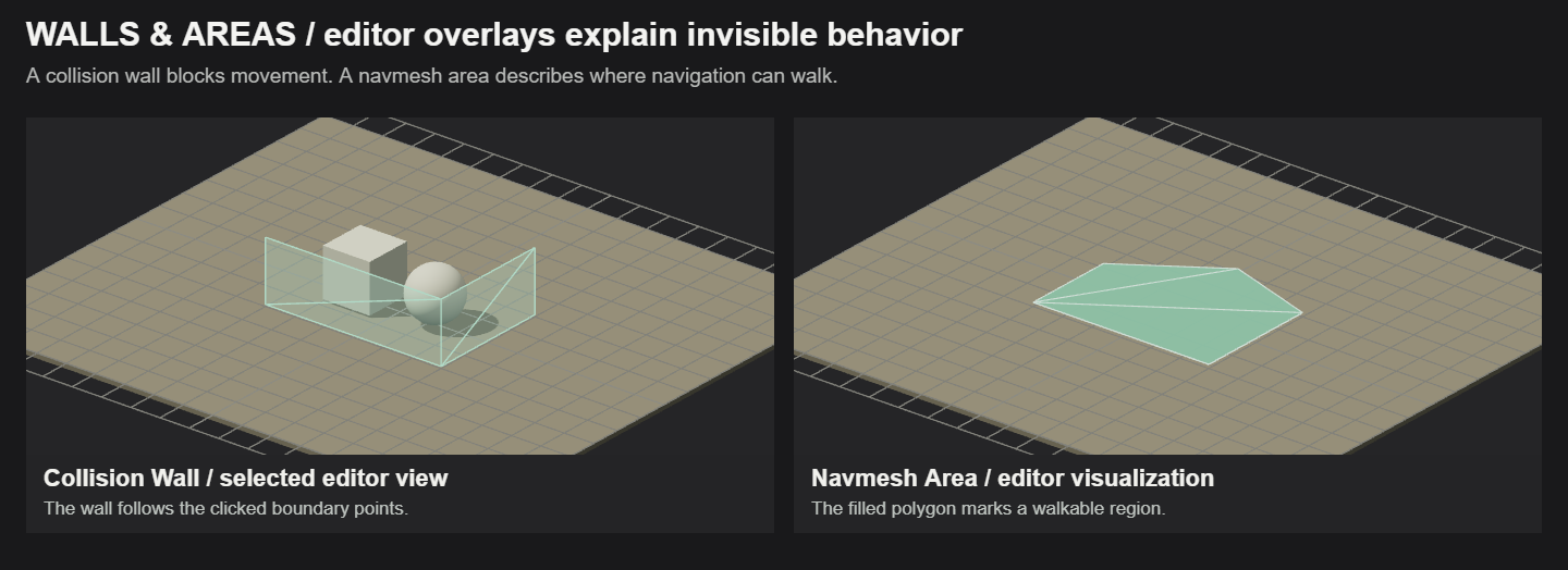
Try it in your scene
- Choose Collision Wall or Navmesh Area under Basics → Walls & Areas and click Draw.
- Click points on the world surface to trace the boundary. Use at least two points for a wall and three for an area; finish with Done.
- For a wall, adjust Height and keep Collision enabled when it should block movement. For an area, check the drawn region follows the intended walking surface.
Settings that change the result
| Setting | What it does |
|---|---|
| Collision Wall | Creates blocking geometry along the clicked points. Height sets the barrier height and Color helps identify it while editing. |
| Collision | Turns wall blocking on or off. The wall visualization is visible when selected and is hidden during play. |
| Navmesh Area | Defines a walkable navigation surface. Draw a clear polygon that avoids obstacles; the area alone does not assign behavior to a character. |
| Points / Done | The clicked points determine the geometry. Finish the drawing before configuring the resulting world item. |
Preview the actual behavior: walk into a collision boundary and test a character that uses navigation on the intended area. Add ordinary shapes separately if players should see a wall or floor.